The Super Hub 3 DOCSIS 3.0 modem/router/Ethernet switch is an Arris TG2492 and will named as such throughout.
Some basic information:
- 2.4 GHz radio and 5 GHz radio for wireless 802.11a/b/g/n/ac connectivity
- Four Ethernet ports
- Up to two lines of telephone service
- DOCSIS 3.0 and Euro-DOCSIS 3.0 compliant
The main goal of the teardown is to extract the firmware, if you want to cut to the chase you can download it hear
https://drive.google.com/open?id=1HNpia3pVRFy6OjKp...
or
http://www.mediafire.com/file/iupc8113d6ty2xs/tg24....
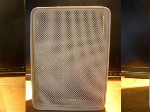
First of all here are some pretty pictures of the Arris TG2492.

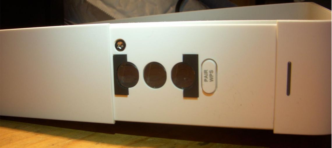
To disassemble you first have to shim the front panel off with a thin piece of plastic or just use a flat head screw driver if you don't care about damaging it.

Remove the Torx screw which is now visible from behind the front pannel.
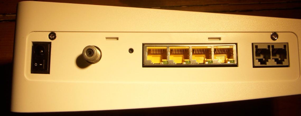
Flip the TG2492 around to the rear and remove the sticker which surrounds the all the ports. You will need a very sharp thin knife to do so.
Once the sticker is removed then proceed to remove the 2 Trox screws which are now visbale.
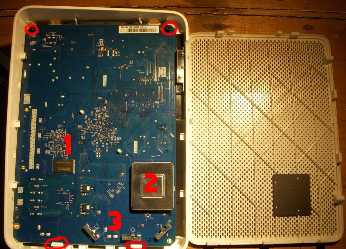
Now place the TG2492 flat so that the plastic mesh side closest to the screws is pointing upwards. Place a flat head screw driver between the case and the plastic mesh in the bottom left corner and gently pry the mesh upwards. Once the mesh is raised enough to get you fingers underneath proceed to pull the rest up by hand.

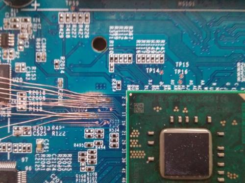
Now we have a rear view of the PCB. To remove the PCB , remove the 2 Torx circled in red at the top of the picture then push back the 2 white clips also circled in red at the bottom of the picture.
| No. | Part Number | Description |
| 1. | Toshiba TC58NVG0S3HTA10 | 128MB NAND FLASH |
| 2A. | QCA9880-3R4A | Qualcomm 802.11ac wireless chipset |
| 2B. | SKY21 85717 | Unkown |
| 3. | Unkown | 5ghz antena and exteranl Micro-Miniature RF Connector |
TC58NVG0S3HTA10 Pinout

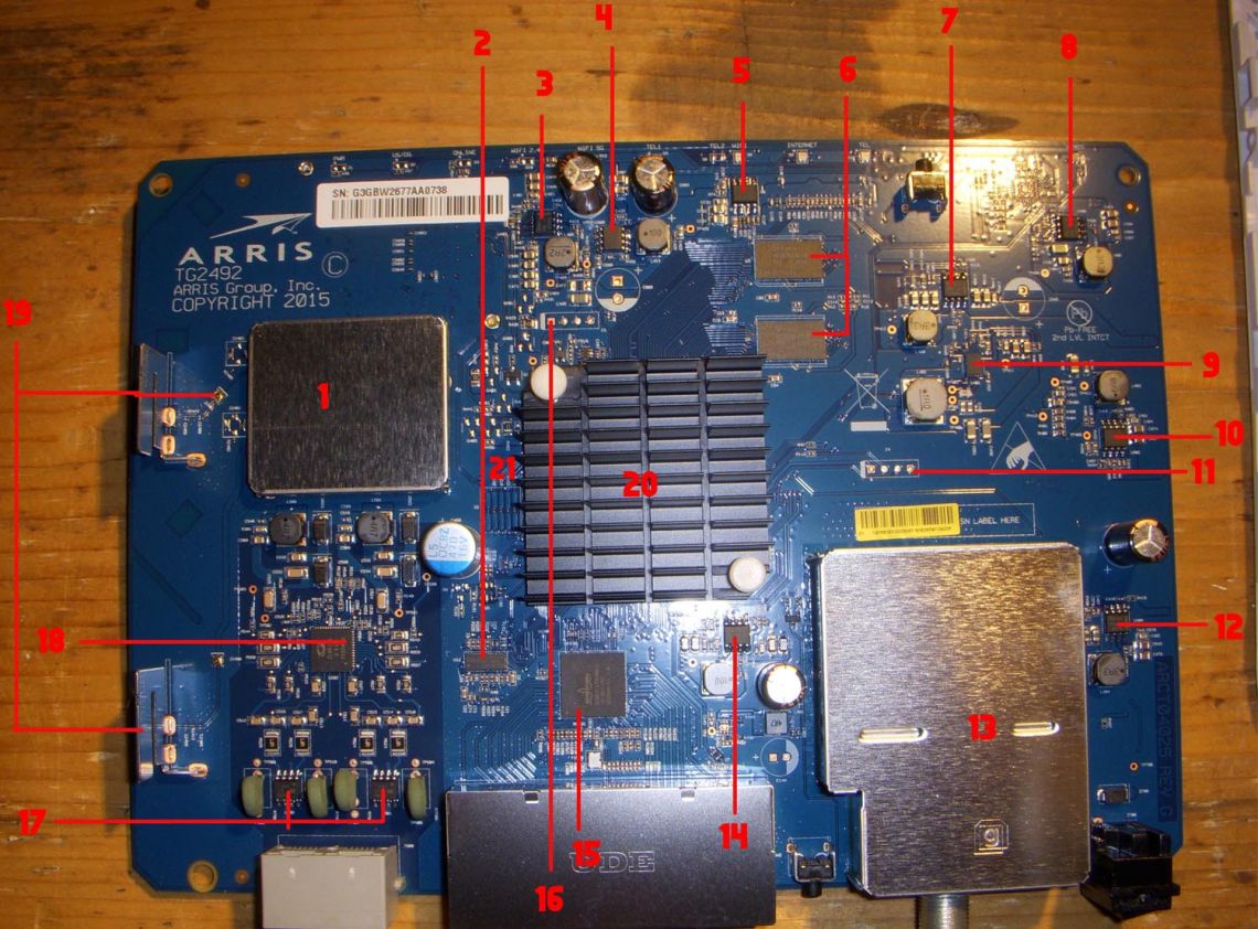
| No. | Part Number | Description |
| 1A. | Atheros AR9382-AL1A | 2.4/5 GHZ, 2-STREAM 802.11A/B/G/N |
| 1B. | SiGe 2620T | 2.4 GHz Wireless LAN/BT Front End |
| 2. | Phison PS8211-0 | Nand Controller eMMC 4.5 |
| 3. | 54328 | Power management chip |
| 4. | Z10166A | Buck chip |
| 5. | R19045 | Unknown |
| 6. | SK Hynix H5TQ2G63FFR-PBC | 128MX16 DDR DRAM, PBGA96 (2048gb Ram. 4096 total) |
| 7. | 54328 | Power management chip |
| 8. | 54328 | Power management chip |
| 9. | NBGA 650A 049 | Unknown |
| 10 | RT8294A | 2A, 23V, 340kHz Synchronous Step-Down Converter |
| 11. | UART | VCC(Square pad), TX, RX, GND. 115200 8-N-1 |
| 12. | 54226 | 4.5V to 18V Input 2-A Synchronous Step-Down SWIFTTM Converter |
| 13A. | MXL267D | Full-Spectrum Capture (FSCTM) digital cable front-end receiver for EuroDOCSIS 3.0 |
| 13B. | 3031 TSD531A | Unknown |
| 14. | 54226 | 4.5V to 18V Input 2-A Synchronous Step-Down SWIFTTM Converter |
| 15. | Broadcom BCM53124SKMMLG | Ethernet ICs GIGABIT SWITCH |
| 16. | UART | VCC(Square pad), TX, RX, GND. 115200 8-N-1 |
| 17. | 61089B | Bourns DUAL FORWARD-CONDUCTING P-GATE THYRISTORS |
| 18. | ZL88105 | Unknown |
| 19. | Unknown | 2.5ghz antenna and external Micro-Miniature RF Connector |
| 20. | Unknown | Intel Puma 6 SoC DHCE2652 (MD553005A02245, 11L602F576SR278, G29275 01 EQE) |
| 21. | JTAG | 10 pads covered (unknown if active). Supported by Intel System Studio with ITP-XDP3 |
Phison PS8211-0 Pinout (maybe the same pinout for PS7000-0, PS8035, PS8130, PS8131, PS8210 )
Thanks to Dan the man for correcting the emmc pinout. Dan has great blog about the Arris router firmware which can be found here https://blog.danman.eu/about-adding-a-static-route-to-my-docsis-modem/
The Phison firmware and config for the PS8211-0 and PS7000-0 can be found on partition 5 at /etc/mmc of router firmware.
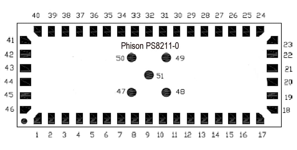
| PIN | NAME | Dir | Description |
| 1 | FAD_PAD[5] | I/O | Flash IO |
| 2 | FAD_PAD[4] | I/O | Flash IO |
| 3 | VCCK_PAD | S | Core Power , 1.2v output |
| 4 | FAD_PAD[3] | I/O | Flash IO |
| 5 | FAD_PAD[2] | I/O | Flash IO |
| 6 | FAD_PAD[1] | I/O | Flash IO |
| 7 | FAD_PAD[0] | I/O | Flash IO |
| 8 | FARDY_PAD | I | Flash Ready/busy |
| 9 | XCLK_GPIO_PAD | I/O | Test pin, floating |
| 10 | XRST_UART_PAD | O | Test pin, floating |
| 11 | FCEB_PAD[1] | O | Flash chip enable |
| 12 | FCEB_PAD[0] | O | Flash chip enable |
| 13 | FARDB_PAD | O | Flash chip enable |
| 14 | VCC3IOM | O | SD/MMC Interface Power |
| 15 | DAT4_PAD | I/O | Data IO |
| 16 | CMD_PAD | I/O | Command / Response |
| 17 | DAT5_PAD | I/O | Data IO |
| 18 | VCCAH | S | Regulator Power |
| 19 | VCC3IOM | S | SD/MMC interface power |
| 20 | LOCK_RST_PAD | I | Reset pin |
| 21 | DAT1_PAD | I/O | Data IO |
| 22 | DAT0_PAD | I/O | Data IO |
| 23 | DAT7_PAD | I/O | Data IO |
| 24 | DAT6_PAD | I/O | Data IO |
| 25 | CLK_PAD | I | Clock |
| 26 | DAT3_PAD | I/O | Data IO |
| 27 | DAT2_PAD | I/O | Data IO |
| 28 | VSSIO_,VSSK, VSSK_,VSSIOM_PAD | S | Ground |
| 29 | MMC_SD_SEL_PAD | I | VCCQ(VCC3IOM):SD supported GND:MMC/eMMC supported |
| 30 | VCCAH_F_PAD | S | Regulator Power input (VCORE/V18) |
| 31 | FACLE_PAD | O | Flash command latch enable |
| 32 | FAALE_PAD | O | Flash address latch enable |
| 33 | FAWP_PAD | O | Flash write protect |
| 34 | FAWP_PAD | O | Flash write protect |
| 35 | ISO_RST_PAD | I/O | Test pin, floating |
| 36 | V12_PAD | S | Core Power2 , 1.2v output |
| 37 | VSSIO_,VSSK_,VSSIOM_PAD | S | Ground |
| 38 | V18_PAD | S | 1.8v output |
| 39 | VCC3IO_PAD | S | Flash Interface power |
| 40 | VSSIO, VSSK,VSSIOM_PAD | S | Ground |
| 41 | VSSIO, VSSK,VSSIOM_PAD | S | Ground |
| 42 | VSSIO, VSSK,VSSIOM_PAD | S | Ground |
| 43 | VSSIO, VSSK,VSSIOM_PAD | S | Ground |
| 44 | FADQS | I/O | Flash IO |
| 45 | FAD_PAD[7] | I/O | Flash IO |
| 46 | FAD_PAD[6] | I/O | Flash IO |
| 47 | TEST_MODE_PAD | I | Test pin: Ground or floating |
| 48 | VSSIO, VSSK,VSSIOM_PAD | S | Ground |
| 49 | VSSIO, VSSK,VSSIOM_PAD | S | Ground |
| 50 | TEST_ISOLT_PAD | I | Test pin: Ground or floating |
| 51 | TEST_RSTCLK_PAD | I | Test pin: Ground or floating |
I: Input , O:Output, S:Power supply
UART Intel Puma 6 DUMP 1 of 3
According to Dan the UART output no longer shows very much at all, this dump is from 2016. This page has been visted many times by an IP address owned by Arris which would explain a few things.
AC_BOOTPOST: 0xb03wdt: reset type = 0, reset reason = 0POST: 0xc02cefdk_rom_base_addr: 0x002e0000POST: 0xc1fwdt: acboot win2 end, counter=1068829POST: 0xf02Warning: No device found in chip select 0Spi Flash Init Failed and disable SPI FlIntel(R) Consumer Electronics Firmware Development Kit (Intel(R) CEFDK)Copyright (C) 1999-2012 Intel Corporation. All rights reserved.Build Time (10/13/14 08:28:14).POST: 0xf07Set flash layout to Arris 128MB Phison layoutPOST: 0xf19Waiting for 5 sec for DOCSIS PLL1 ready...DOCSIS PLL1 readyPOST: 0xfa0SMM: OkPOST: 0xf24ACPI Init: finished with table region from 00011ab0 to 00018000acpi: Created tables at 00011ab0-00018000POST: 0xf29CEFDK Version : ARRIS build 1682:2.01.17 (SMP enabled)Built from SDK : IntelCE-4.5.14421.3472118051 Firmware : A0-1.2.0 build R 0x20A8051 FW I/O Module :Silicon Stepping : D0Silicon SKU : 0x14FBoard Set As : Harbor Park - MGCPU Threads : 2CPU Multiplier : 12CPU Bus Speed : 100 MHzMemory Size : 512 MBMemory Type & Speed : x16 DDR3-1333 (10-10-10)Trusted Boot : UntrustedBoot Mode : eMMC-NAND (STRAPS)Registered net controller: e1000Init External Switch for board Type: 1ARRIS : INIT EXTERNAL BCM SWITCH1000M FD Link is ready!Configure IP via static IP.Mac address is : 00:00:CA:01:02:03Host IP address is: 192.168.100.1Subnet Mask is : 255.255.255.0Gateway address is: 192.168.100.1================================================WARNING: Please make sure the board type and DOCSIS DDR offset/size are set correctly, otherwise DOCSIS subsystem won't boot! If not sure, please use "settings" shell command to show the setup menu, then check "Advanced Features".================================================Press 'Enter' within 0 seconds to disable automatic boot.Hit a key to start the shell...Running auto script...shell> ord4 0xC80D0000 0x03000000shell> ord4 0xdf9fa004 0xBshell> load -m 0x200000 -i a -t emmcget Active Image info success:3a40000, 400000, 1, 1, 3eMMC kernel command: root=/dev/mmcblk0p12Load data from emmcLoad done.shell> bootkernel -b 0x200000 "console=ttyS0,115200 ip=static memmap=256M$256M"Working Cmd: console=ttyS0,115200 ip=static memmap=256M$256M root=/dev/mmcblk0p1 2CMD(0x48000)='console=ttyS0,115200 ip=static memmap=256M$256M root=/dev/mmcblk0p 12 'WARNING: Ancient bootloader, some functionality may be limited!Initializing cgroup subsys cpusetInitializing cgroup subsys cpuLinux version 2.6.39 (ccbuild@canes.arrisi.com) (gcc version 4.5.1 (IntelCE tool chain-V5 Tue Apr 17 19:34:48 PDT 2012) ) #2 SMP PREEMPT Fri Dec 11 16:06:06 EST 2015BIOS-provided physical RAM map: BIOS-e820: 0000000000000000 - 0000000000011ab0 (reserved) BIOS-e820: 0000000000011ab0 - 0000000000018000 (ACPI data) BIOS-e820: 0000000000018000 - 0000000000020000 (reserved) BIOS-e820: 0000000000020000 - 0000000000040000 (usable) BIOS-e820: 0000000000040000 - 0000000000100000 (reserved) BIOS-e820: 0000000000100000 - 0000000007400000 (usable) BIOS-e820: 0000000007400000 - 0000000008000000 (reserved) BIOS-e820: 0000000008000000 - 0000000010000000 (usable) BIOS-e820: 0000000010000000 - 0000000030000000 (reserved) BIOS-e820: 00000000fec00000 - 00000000fec00400 type 6 BIOS-e820: 00000000fee00000 - 00000000fee00400 type 7extended physical RAM map: reserve setup_data: 0000000000000000 - 0000000000011ab0 (reserved) reserve setup_data: 0000000000011ab0 - 0000000000018000 (ACPI data) reserve setup_data: 0000000000018000 - 0000000000020000 (reserved) reserve setup_data: 0000000000020000 - 0000000000040000 (usable) reserve setup_data: 0000000000040000 - 0000000000100000 (reserved) reserve setup_data: 0000000000100000 - 0000000007400000 (usable) reserve setup_data: 0000000007400000 - 0000000008000000 (reserved) reserve setup_data: 0000000008000000 - 0000000010000000 (usable) reserve setup_data: 0000000010000000 - 0000000030000000 (reserved) reserve setup_data: 00000000fec00000 - 00000000fec00400 type 6 reserve setup_data: 00000000fee00000 - 00000000fee00400 type 7NX (Execute Disable) protection: activeuser-defined physical RAM map: user: 0000000000000000 - 0000000000011ab0 (reserved) user: 0000000000011ab0 - 0000000000018000 (ACPI data) user: 0000000000018000 - 0000000000020000 (reserved) user: 0000000000020000 - 0000000000040000 (usable) user: 0000000000040000 - 0000000000100000 (reserved) user: 0000000000100000 - 0000000007400000 (usable) user: 0000000007400000 - 0000000008000000 (reserved) user: 0000000008000000 - 0000000010000000 (usable) user: 0000000010000000 - 0000000030000000 (reserved) user: 00000000fec00000 - 00000000fec00400 type 6 user: 00000000fee00000 - 00000000fee00400 type 7DMI not present or invalid.last_pfn = 0x10000 max_arch_pfn = 0x1000000init_memory_mapping: 0000000000000000-0000000010000000ACPI: RSDP 0009fc00 00024 (v02 INTEL )ACPI: RSDT 00017fb0 00030 (v01 INTEL 00000000 00000000)ACPI: FACP 00013b20 000F4 (v03 INTEL 00000000 00000000)ACPI: DSDT 00013c20 010D4 (v01 Intel CE2600 00000001 INTL 20091112)ACPI: FACS 00017f70 00040ACPI: APIC 00011af0 00068 (v01 INTEL 00000000 00000000)ACPI: HPET 00011ab0 00038 (v01 INTEL 00000000 00000000)0MB HIGHMEM available.256MB LOWMEM available. mapped low ram: 0 - 10000000 low ram: 0 - 10000000Zone PFN ranges: DMA 0x00000020 -> 0x00001000 Normal 0x00001000 -> 0x00010000 HighMem emptyMovable zone start PFN for each nodeearly_node_map[3] active PFN ranges 0: 0x00000020 -> 0x00000040 0: 0x00000100 -> 0x00007400 0: 0x00008000 -> 0x00010000Using APIC driver defaultACPI: PM-Timer IO Port: 0x1008ACPI: LAPIC (acpi_id[0x00] lapic_id[0x00] enabled)ACPI: LAPIC (acpi_id[0x01] lapic_id[0x01] enabled)ACPI: IOAPIC (id[0x00] address[0xfec00000] gsi_base[0])IOAPIC[0]: apic_id 0, version 32, address 0xfec00000, GSI 0-23ACPI: IOAPIC (id[0x01] address[0xbffff000] gsi_base[24])IOAPIC[1]: apic_id 1, version 32, address 0xbffff000, GSI 24-47ACPI: INT_SRC_OVR (bus 0 bus_irq 0 global_irq 2 high level)ACPI: INT_SRC_OVR (bus 0 bus_irq 9 global_irq 9 high level)Using ACPI (MADT) for SMP configuration informationACPI: HPET id: 0x8086a201 base: 0xfed00000SMP: Allowing 2 CPUs, 0 hotplug CPUsAllocating PCI resources starting at 30000000 (gap: 30000000:cec00000)setup_percpu: NR_CPUS:8 nr_cpumask_bits:8 nr_cpu_ids:2 nr_node_ids:1PERCPU: Embedded 12 pages/cpu @cfa00000 s25792 r0 d23360 u1048576Built 1 zonelists in Zone order, mobility grouping on. Total pages: 61728Kernel command line: console=ttyS0,115200 ip=static memmap=256M$256M root=/dev/m mcblk0p12PID hash table entries: 1024 (order: 0, 4096 bytes)Dentry cache hash table entries: 32768 (order: 5, 131072 bytes)Inode-cache hash table entries: 16384 (order: 4, 65536 bytes)Initializing CPU#0allocated 1048064 bytes of page_cgroupplease try 'cgroup_disable=memory' option if you don't want memory cgroupsInitializing HighMem for node 0 (00000000:00000000)Memory: 237120k/262144k available (5732k kernel code, 11840k reserved, 1901k dat a, 400k init, 0k highmem)virtual kernel memory layout: fixmap : 0xfff18000 - 0xfffff000 ( 924 kB) pkmap : 0xffc00000 - 0xffe00000 (2048 kB) vmalloc : 0xd0800000 - 0xffbfe000 ( 755 MB) lowmem : 0xc0000000 - 0xd0000000 ( 256 MB) .init : 0xc1775000 - 0xc17d9000 ( 400 kB) .data : 0xc159929d - 0xc1774a80 (1901 kB) .text : 0xc1000000 - 0xc159929d (5732 kB)Checking if this processor honours the WP bit even in supervisor mode...Ok.SLUB: Genslabs=15, HWalign=64, Order=0-3, MinObjects=0, CPUs=2, Nodes=1Preemptable hierarchical RCU implementation. RCU-based detection of stalled CPUs is disabled. Verbose stalled-CPUs detection is disabled.NR_IRQS:512Extended CMOS year: 2000Console: colour dummy device 80x25console [ttyS0] enabledFast TSC calibration using PITDetected 1200.047 MHz processor.Calibrating delay loop (skipped), value calculated using timer frequency.. 2400. 09 BogoMIPS (lpj=4800188)pid_max: default: 32768 minimum: 301Mount-cache hash table entries: 512Initializing cgroup subsys nsns_cgroup deprecated: consider using the 'clone_children' flag without the ns_cg roup.Initializing cgroup subsys cpuacctInitializing cgroup subsys memoryInitializing cgroup subsys devicesInitializing cgroup subsys freezerInitializing cgroup subsys blkioInitializing cgroup subsys perf_eventCPU: Physical Processor ID: 0


